Criticality classification decides how much maintenance effort each asset deserves. NORSOK Z-008:2024 §8.3 wants you to do it the function-decomposed way: define what the system does (Main Functions), break each function into the smaller things it does (Sub Functions), then map your physical tags to the Sub Functions. The tool inherits classifications down the tree per Annex B, so you usually fill in just the Main Function level and the rest auto-populates.
The output is a Dominant Class per tag (C1 low, C2 medium, C3 high), plus redundancy (RED-A/B/C), containment, and barrier flags. That output drives FMECA depth, RCM scope, GMC selection, inspection intervals, and corrective-maintenance response time. The 5/30/180-day figures are the defaults this tool ships with, read off the example risk model in Annex C, Table C.3 — the standard prints it as “an example of a risk model”, Annex C is informative, and §5.4 requires risk decisions to follow criteria your company has defined and communicated. Treat them as a starting point to replace, not as the standard’s numbers.
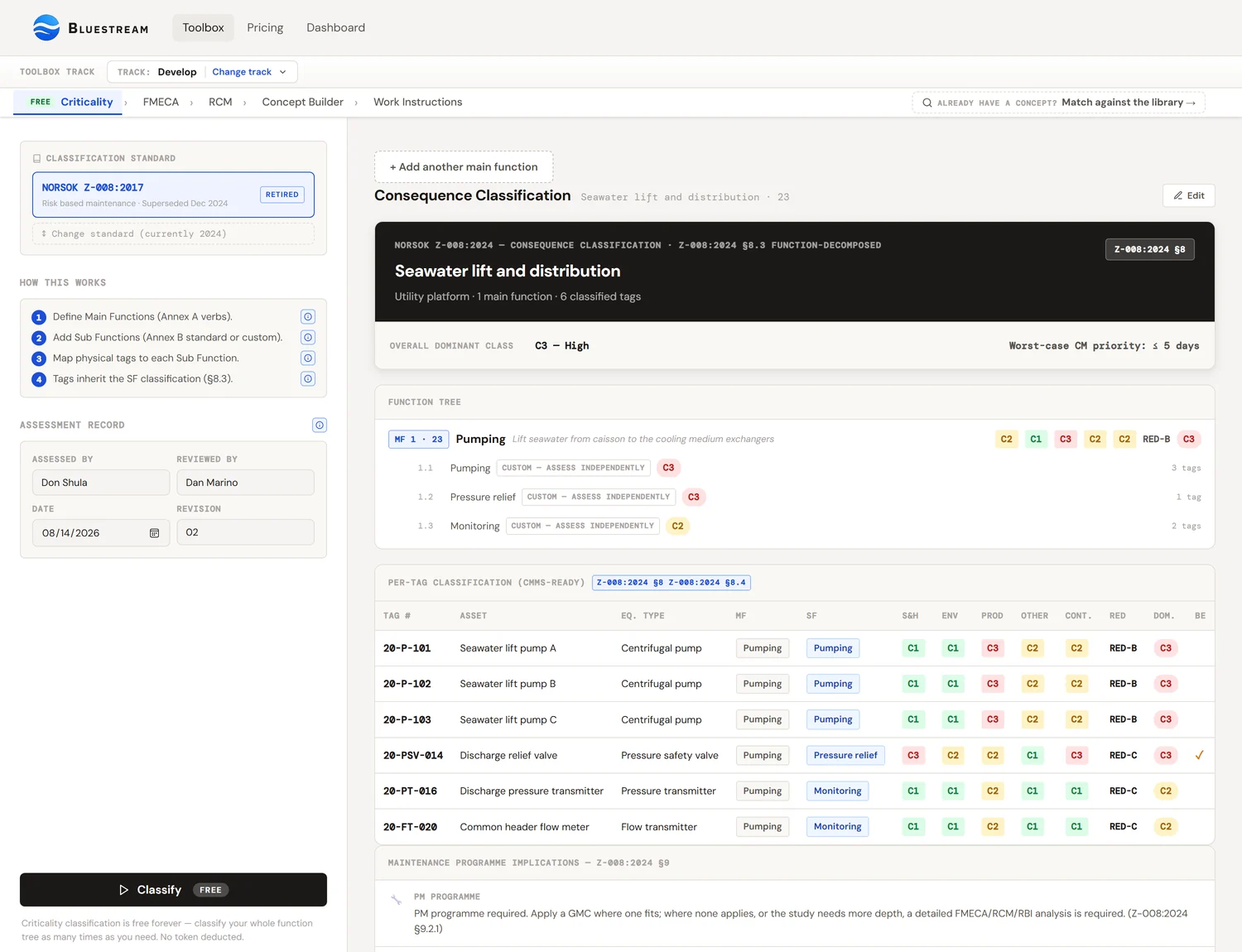
The big idea: classify functions, not equipment
Most plants do criticality classification at the equipment level. They pick up a pump tag, write down "C2", move on to the next tag. It works on a spreadsheet, but it has two problems.
First problem: two pumps that share one job get classified twice, and often inconsistently. P-101A and P-101B are supposed to do the same thing. If a different engineer rates each one, you can end up with P-101A as C2 and P-101B as C3 just because of the day they were assessed.
Second problem: tag-level classification ignores context. A 50 kW pump on a critical service is C3. The same pump on a service-water system is C1. You cannot tell from the pump itself, only from what it is doing. Classification anchored to the asset rather than the function loses that context.
Z-008:2024 §8.3 fixes both problems by classifying the function first. The function carries the consequence rating. Tags inherit it from whichever Sub Functionthey perform. Two pumps doing the same job get one rating, automatically. The same pump on a different service gets a different rating, automatically.
If you remember one thing: when classifying, do not look at the pump. Look at what the pump is doing. Classify the doing. The pump inherits.
Three building blocks: Main Function, Sub Function, Tag
The new flow has three levels. Each one is a layer of detail finer than the one above.
Main Function (MF)
What a part of the plant does. Always an active verb. Pumping is a Main Function. Pump P-101A is not. Z-008 Annex A lists about 30 typical verbs (Pumping, Compressing, Separating, Storing, Heating, Cooling, Filtering, Distributing, Lifting, Metering, Detecting, Generating, Transferring, Mixing, Reacting, Fire fighting, Life saving, etc.). The list is informative, not exhaustive. If your function is not on the list, type your own.
Each MF gets a number (optional) and a descriptor that explains the scope and boundary: "Lift seawater from the caisson to the surface deck at 25 bar minimum discharge". That descriptor matters. It draws the line around what is in and out of this function.
Sub Function (SF)
One of the things a Main Function does. A Pumping function might have Sub Functions for pressure relief, shut down on demand, monitoring, controlling, and manual isolation. Z-008 Annex B lists seven recurring Sub Functions and tells you exactly how their classification relates to the parent MF. If you pick one of those names, the tool fills in the consequence cells for you per the inheritance rules in Annex B Table B.1.
If the Sub Function does not match any of the seven, mark it Custom and assign all values manually. The tool flags it so reviewers can see the difference.
Tag
A physical asset with a unique CMMS identifier: pumps, valves, transmitters, vessels. Every tag belongs to one Sub Function. The tag inherits the Sub Function's full classification automatically. If a tag does more than one thing (an instrument loop measures, monitors, and triggers shutdown), Z-008 says assign it to the most critical Sub Function.
A worked example
Let us walk through a small system end to end. We have a Seawater Lift System on a Florida-based heat exchanger plant. Two centrifugal pumps share the lifting duty. There is one pressure-relief valve on the discharge header, two flow transmitters for monitoring, and one manual isolation valve at the inlet.
Step 1: Define the Main Function
Open Tool 2 in the Toolbox. Type the system name "Seawater Lift System" into the System field. Add a Main Function: Pumping (from the Annex A list), with descriptor "Lift seawater from caisson to deck at 4 bar minimum discharge". Number it MF-1 if you want.
Now classify the Main Function. We rate the consequence of losing the pumping function entirely (assume both pumps gone, redundancy disregarded at this step):
Environment: C1, seawater, no contamination risk
Production: C3, the heat exchanger downstream cannot run without the lift
Other / Cost: C2, moderate repair cost if both pumps damaged
Containment: C1, non-hazardous fluid, normal P/T
Redundancy: RED-B, one pump can fail without losing the function
Step 2: Add Sub Functions
Pumping needs sub functions for monitoring (the transmitters), pressure relief (the PSV), and manual isolation (the inlet valve). Add three SFs under the MF, picking the names from the Annex B list. The tool fills in the cells:
SF Pressure relief (Annex B): S&H = C3 (forced "H"), Prod = C1 (forced "L"), RED = B (inherited)
SF Manual shutoff (Annex B): every cell inherits MF reduced by one level (C3→C2, C2→C1, C1 stays C1)
Notice the Pressure Relief SF jumped to C3 on Safety & Health even though the parent MF was C1. That is the Annex B rule: a relief function carries safety consequence regardless of what the parent does. The tool applied that automatically.
Step 3: Map tags to Sub Functions
Now drop in the physical equipment.
Under SF Pressure relief: PSV-101 (Pressure Safety Valve)
Under SF Manual shutoff: XV-101 (manual gate valve)
The two pumps P-101A/B are not under any of these SFs. They perform the Main Function directly, so we add a Sub Function called "Primary delivery" (Custom, since it is not in Annex B), inherit MF values, and map the pumps there.
Step 4: Classify and review
Hit Classify (1 token, regardless of how many MFs / SFs / tags). The tool produces a per-tag table:
P-101B → SF Primary delivery → Dom C3 (Production)
PT-101 → SF Monitoring → Dom C2 (Safety & Health)
FT-101 → SF Monitoring → Dom C2 (Safety & Health)
PSV-101 → SF Pressure relief → Dom C3 (Safety & Health)
XV-101 → SF Manual shutoff → Dom C2 (Production reduced)
Now we have an auditable, function-anchored classification for every tag. The PSV's C3 came from Annex B's safety rule, not from a guess. The pumps' C3 came from the production consequence of losing the function. The transmitters got C2 because monitoring is monitoring, regardless of what is being monitored.
The four consequence categories
For every Main Function (and every Sub Function that breaks inheritance), you rate the consequence of failure independently in four categories. Both editions list Environment as its own consequence category in Table C.1 — it was never bundled into "HSE". What 2024 changed is that the safety row is renamed "Safety and health" and the Containment row that 2017 carried is dropped, with loss of containment assessed as a separate failure mode (§8.2) and inspection set through RBI (§5.3). Note Annex B still uses a single combined HSE column in both editions, which is why the tool carries an Environment value the table does not.
Safety & Health
Consequence to personnel from a failure of the function. C3 is fatality or serious injury. C2 is medical-treatment injuries. C1 is no injury potential. Click the ? next to the label in the tool for Annex C, Table C.1.
Environment
Discharges and emissions to the external environment. C3 is major release. C2 is medium release. C1 is no release or minor only. New as a standalone category in 2024. Annex E was added for climate and greenhouse-gas screening.
Production
Throughput, availability, downstream service. C3 is downtime exceeding the company-defined threshold (X days). C2 is delayed production or reduced throughput. C1 is no production loss. The X threshold is set by the company per §5.4.
Other / Cost
Operational or asset-cost impact not already captured: unplanned repair cost, loss of capital value, work environment, reputation. C3 is significant. C2 is moderate. C1 is none.
Containment is a fifth column, but Z-008 treats it as a separate failure mode (loss of containment, not loss of function). The tool keeps it inline for convenience. C3 is hydrocarbons above flashpoint, highly toxic gases, extreme P/T. C1 is non-hazardous fluids at normal conditions. Use N/A if the function does not involve a pressurised or hazardous fluid.
Dominant class: the "C3 wins" rule
Once each category is rated, the dominant class for that function is the worst rating across all categories. Not the average. Not the most frequent. The worst.
Why "worst, not average"? Because consequences do not cancel out. An asset that is C3 on Safety and C1 on everything else is still a safety-critical asset. Averaging would hide that. The dominant class makes sure the biggest risk drives the maintenance programme.
Annex B inheritance: the time-saver
Z-008:2024 Annex B is informative, and Table B.1 is printed as “an example of consequence assessment of standardized SFs” — a worked default for how seven recurring Sub Functions relate to their parent Main Function, not a conformance rule. The tool applies that example automatically when you pick one of the standard names, which saves the typing; the annex then asks that the result be “verified by experienced process personnel and adjusted individually”, so every inherited cell stays editable and you are expected to look at it.
| Standard SF | RED | S&H | Env | Prod | Other |
|---|---|---|---|---|---|
| Main function | MF | MF | MF | MF | MF |
| Pressure relief | MF | H | MF | L | L |
| Shut down, process (ESD/PSD) | A | H | MF | L | L |
| Shut down, equipment | MF | M | MF | L | MF |
| Controlling | MF | MF | MF | MF | MF |
| Monitoring | MF | M | MF | L | L |
| Local indication | MF | L | MF | L | L |
| Manual shutoff | MF | (MF) | (MF) | (MF) | (MF) |
Reading the table: MF means inherit the parent value as is. H / M / L means a fixed C3 / C2 / C1 regardless of the parent. (MF) means inherit but reduce by one class (C3 becomes C2, C2 becomes C1, C1 stays C1). A in the RED column means redundancy is forced to A.
The point of these rules is that safety-critical functions carry safety-critical consequence regardless of what the parent does. Pressure relief is always C3 on safety. Monitoring is always C2 (you have alarms, but no automatic action). Local indication is always C1 (someone has to walk over and look). The standard hard-wires the conservative cases so you cannot accidentally skip them.
Custom Sub Functions
The seven standard Sub Functions cover the common cases for process equipment, but not everything. If your Sub Function is something specific to your industry (cleaning-in-place loop, bag changeout, regenerator cycling), pick "Custom" and assign all six values manually.
Earlier versions of the tool pre-filled custom SFs from the MF; it no longer does, because Z-008 Annex B requires custom sub functions to be assessed independently. The tool now leaves them blank and refuses to run until they are set. Historically it defaulted custom SFs to inherit the MF values straight across, which is a safe starting point. You then adjust whichever cells need different values, and write a rationale.
Custom should be the exception, not the rule. If you find yourself making everything Custom, the standard names are probably fitting; pick the closest one and override the cells that do not fit. Reviewers find Custom rows harder to validate than standard ones with overrides, because the inheritance baseline is missing.
When to override the inheritance
You can click any Sub Function cell and pick a value different from the inherited one. The tool marks the cell with an amber "override" badge. Click the ↺ arrow to revert.
Reasonable times to override:
- The Sub Function is in an unmanned area. Annex B's "M" rating for monitoring assumes someone will see the alarm. If nobody is in the building, that assumption breaks.
- The function has compensating controls outside the SF: a downstream operator station that catches the failure independently, an automated isolation valve.
- The function operates in a different mode than the standard assumes. Regulatory redundancy that should not be credited (defence-in-depth) is the classic example.
- The parent MF rating is borderline and the SF should not propagate the worst case.
Unreasonable times to override:
- To make a difficult asset look easier on the report.
- Because "we have always done it this way" without documenting why.
- Because the conservative default would push the asset into a maintenance bucket the budget cannot absorb.
If you override, write a rationale in the field below the SF row. Auditors read those.
Redundancy: function level, not equipment level
Redundancy here describes how the function survives a single fault, not how a specific tag survives. Two pumps that share one pumping function: that is RED-B (one parallel unit can fail without losing the function). Three pumps where two can fail and the function still operates: RED-C.
| RED | Definition |
|---|---|
| A | No redundancy. Single point of failure for the function. |
| B | One parallel unit can fail without losing the function. |
| C | Two or more parallel units can fail without losing the function. |
Watch out: redundancy installed for safety reasons (regulatory SIL, defence-in-depth) does not count here. Treat those functions as RED-A. Redundancy that exists for availability reasons can count. Z-008 §8.3 step 6 makes this distinction explicit.
Containment: the separate failure mode
Containment is treated as a separate failure mode from loss of function. A pressurised vessel can fulfil its function perfectly and still rupture. That is a containment failure, not a function failure. The maintenance programme has to handle both.
Quick guide:
| Class | Typical contents |
|---|---|
| C3 | Hydrocarbons above flashpoint, highly toxic gases (H₂S, Cl₂), extreme P/T (above ANSI 600#, cryogenic) |
| C2 | Hydrocarbons below flashpoint, moderate toxicity, high P/T (ANSI 150 to 600#) |
| C1 | Non-flammable, non-toxic fluids at normal P/T (water, air, low-pressure utility) |
| N/A | The function does not involve a pressurised or hazardous fluid (rotating equipment without process fluid, electrical equipment, structural members) |
RBI overlap: if you already have a Risk-Based Inspection assessment for the same containment boundary, use those results as the input here. Do not re-assess. Z-008 §8.3 explicitly treats RBI output as input to the consequence classification of containment.
Barrier elements (ISO 17776)
A technical barrier element is a piece of equipment that realises a safety or environmental barrier function. ESD valves, fire and gas detectors, deluge systems, pressure-relief valves, blowdown valves. Barriers come from a separate process: quantitative risk assessment, design HAZOP, or a major-accident barrier strategy.
Z-008 does define barrier: §3.8 of the 2024 edition (§3.1.3 in 2017) gives “functional grouping of safeguards or controls selected to prevent a major accident or limit the consequences”, adopted from ISO 17776:2016, 3.1.1, and adds that barriers subdivide into technical, operational and organisational barrier elements and that the document focuses on the technical ones. What Z-008 does not do is identify them: §8.2 says “Barriers are defined separately via safety analysis (e.g. quantitative risk analysis) in the design or modification process”, and §5.2 points to ISO 17776 and NORSOK S-001 for the requirements on technical barrier elements and their performance standards. It then places real requirements on the maintenance side: §9.3 of the 2024 edition says the elements (tags) performing a barrier function shall be identified and their performance requirements shall be described so the person performing the verification can test, verify and report the condition of the item; the 2017 edition puts it more softly in §8.4, where the items performing a barrier function need to be identified and the performance of the technical barrier element shall be described so a maintenance operator can test, verify and report the condition of the item. Flagging a function or tag as a barrier in this tool is how that identification is recorded; the flag also puts the asset on a tighter inspection schedule and a shorter corrective-maintenance response time — this tool ships ≤ 2 days for C3 barriers, taken from the example risk model in Annex C, Table C.3, which is informative and which §5.4 expects you to replace with your own defined criteria.
When you flag a function as a barrier, reference the Performance Standard that defines its required performance. Examples: PS-ESD-001, SIL 2 per IEC 61511, F&G PS-FG-002. The Performance Standard is the contract between operations and maintenance for what "working" means.
Documentation requirements (§8.4)
Z-008:2024 §8.4 lists the minimum content that the classification record must contain. The fields at the top of the tool cover all of them:
- Decision criteria: which company-specific risk thresholds apply (§5.4 allows deviation from Annex C)
- Basis for assessment: source documents (P&ID rev, OREDA dataset, vendor manual, RBI report, etc.)
- Assumptions: operating mode, redundancy availability, manning level, etc.
- MF and SF descriptions: captured in each row of the function tree
- Tag-to-SF assignment: captured in each tag row
- Consequence and redundancy assessments with rationale: per MF, with override rationales on SFs that deviate from Annex B
- Assessor / reviewer / date / revision: sidebar fields
Skipping these fields does not make the classification wrong, but it does make the study non-conformant: Z-008 §8.4 requires the basis for the classification to be documented, and an undocumented result cannot be verified, reused or defended in an audit. The .docx export reproduces all of them in the official record.
What classification drives downstream
The dominant class from this tool is the leverage point for everything that comes after. Concretely, the dominant class governs:
- FMECA: mandatory for C3, recommended for C2, optional for C1 (§9.2.1)
- Analysis depth: a higher class justifies more analysis, but Z-008 does not map classes to methods. §9.4 chooses a generic maintenance concept over individual analysis on whether the items form a generic group sharing design, failure modes, failure frequencies and operating conditions — not on consequence class — and a detailed FMECA/RCM/RBI is required where no GMC applies or the study needs more depth
- Inspection interval ceilings (§9.2.2, §9.3)
- Corrective-maintenance response time — the defaults this tool ships, read off the example in Annex C, Table C.3 and replaceable under §5.4:
- C3 dominant: ≤ 5 days; barrier elements ≤ 2 days
- C2 dominant: ≤ 30 days
- C1 dominant: ≤ 180 days
- Whether a planned corrective strategy is acceptable as the outcome — §9.2.1 allows it where no preventive or assurance activity is required or cost-effective, and separately requires that failure modes rendering an item unsafe be controlled whatever its class (§9.2.2)
- Spare-parts strategy: stocked locally, regionally, or pooled
The Bluestream toolbox carries the dominant class forward automatically into FMECA (Tool 3), RCM (Tool 4), Concept Builder (Tool 5), and Work Instructions (Tool 6). You do not re-enter it.
Common mistakes
- Classifying tags directly instead of through functions. The most common mistake. Z-008:2024 §8.3 wants every tag mapped to a Sub Function. Tag-direct classification works on a spreadsheet but will not pass an audit.
- Classifying with redundancy already credited. When you set the MF consequence, ignore redundancy at that step. Redundancy enters separately at the RED rating. Mixing them double-counts.
- Crediting safety-redundancy. Two ESD valves in series is RED-A for classification purposes, even if they are physically two valves. The redundancy exists for safety, not availability.
- Overriding without writing a rationale. An override without a written reason is invisible to reviewers and unauditable.
- Treating Custom SFs as the default. Custom is for genuinely unusual sub functions. The seven Annex B types cover most process equipment. Use them.
- Forgetting that containment is a separate failure mode. A vessel can do its job and still leak. Both modes need maintenance attention.
- Setting Production threshold by guesswork. The X-day threshold for "downtime exceeding..." should come from the corporate risk matrix, not from the assessor's intuition.
References
- NORSOK Z-008:2024, Risk based maintenance and consequence classification, 20 December 2024, particularly §7 (Technical hierarchy), §8.3 (Stepwise classification work process and Table 1), §8.4 (Documentation), Annex A (Main Function descriptions), Annex B (Standard Sub Function inheritance), and Annex C (Risk assessment criteria).
- NORSOK Z-008:2017, the previous edition (superseded). The Bluestream tool still supports it for legacy programmes; switch in the sidebar.
- ISO 17776:2016, Major accident hazard management during the design of new installations, for the definition of barrier elements.
- IEC 61511, the SIL standard, for performance specification of safety-instrumented systems.
- ISO 14224:2016 Annex A and B, for equipment-class taxonomy used in FMECA (Tool 3).